January 12, 2021
By Pavel Stankoulov
Introduction
This is the last part of the three-part blog series that explores micro-location technologies. Part 2 described the current most popular way of doing micro-location using Bluetooth Low Energy (BLE) and the received signal strength indicator (RSSI) as an approximation for distance. As explained, there are issues related to using RSSI-based approach to estimate distances and perform micro-location. To overcome these limitations, the Bluetooth Special Interest Group (SIG) introduced direction finding capabilities to the Bluetooth with its 5.1 standard.
This blog describes what was added ion Bluetooth 5.1 and more specifically the direction-finding capabilities added to BLE. The blog explores the supported techniques and how they can improve the accuracy for micro-location applications.
Bluetooth 5.1
Bluetooth (BT) 5.1 became officially a standard in January 2019. It added “direction finding” feature to the BLE protocol. This new feature holds the potential to significantly enhance the performance of BLE-based micro-location solutions. With the ability to determine the direction of a Bluetooth signal, devices can achieve centimeter-level location accuracy.
The rest of the blog describes the supported modes of direction-finding and how it can be used for smartphone micro-location.
Support for Bluetooth 5.1 standard has been added by all major Bluetooth System on Chip (SoC) providers. The direction-finding feature requires a more complex antennas arrangement. Although, BT 5.1 compatible SoCs are making their way into the modern smartphones, software support is not there yet.
Direction Finding
For the direction finding to work, either the receiver or the sender must have two or more antennas (antenna array). The direction can be calculated based on the time or phase difference of the detected signal as explained below.
To simplify the direction finding, the protocol adds a continuous tone extension (CTE) at the end of a BLE packet. Otherwise the packets are not modified and used as part of the standard BLE communication. CTE is a pure (i.e., unmodulated) tone that contains sequence of binary one values. It is long enough for the receiver to measure the phase difference.
There are two angle measurement methods supported by the protocol:
Angle of Arrival (AoA)
In the Angle of Arrival (AoA) mode, the transmitter has one antenna, and the receiver has multiple antennas (antenna array) as illustrated below.
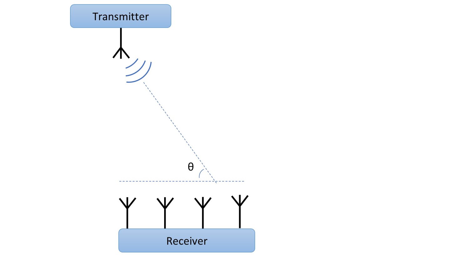
The transmitter constantly broadcasts messages that contain the CTE. The receiver receives those messages and decodes them using the standard BLE mechanism and then use the CTE to calculate the phase difference of the received signal between the antennas. This is done by switching between each active antenna in the array. There is a phase difference of signal of each antenna because of the distance between the antennas and the angle of the radio signal. This is illustrated below:
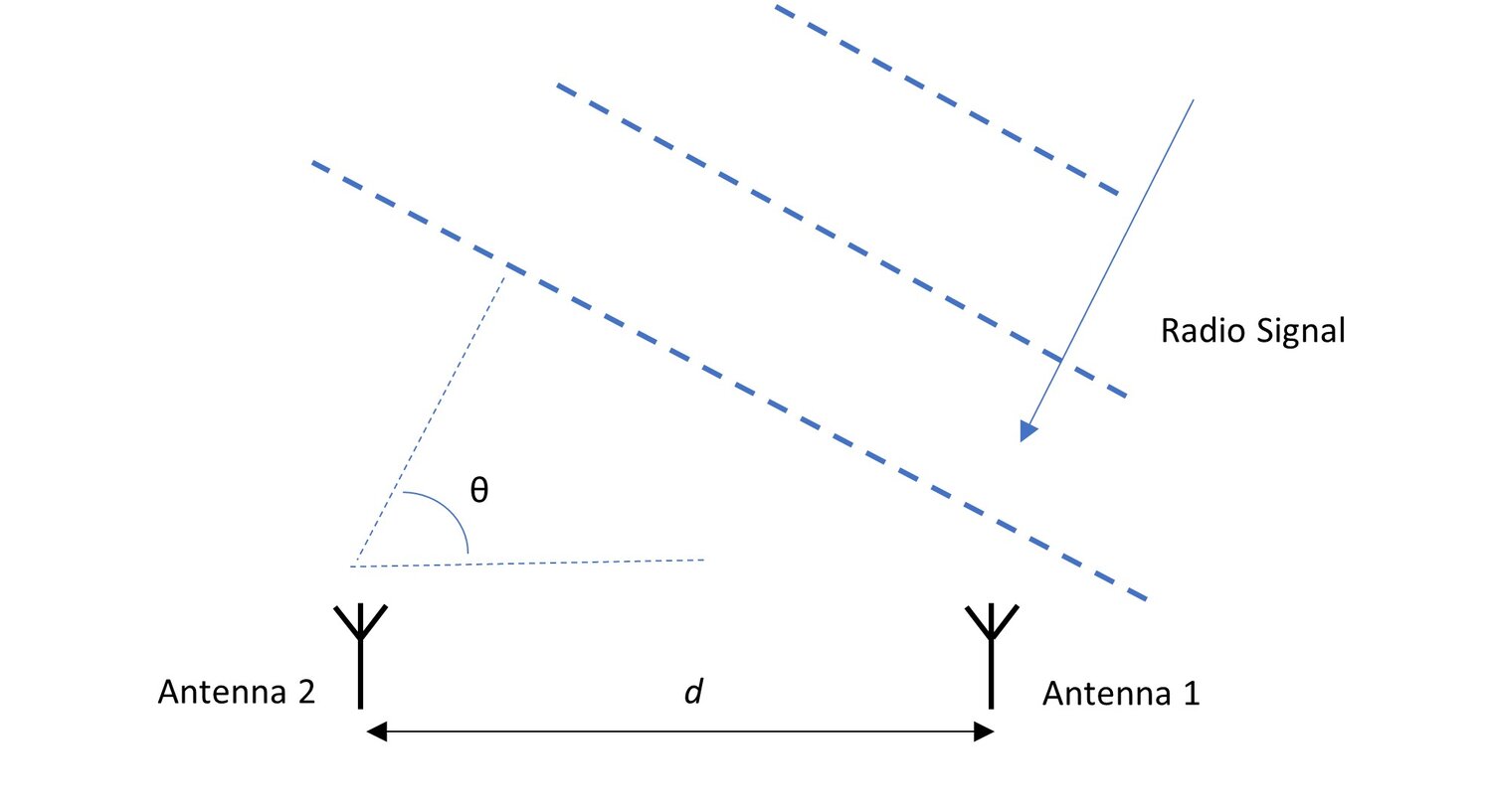
Based on the above picture, the radio signal angle of arrival θ can be calculated using the measured phase difference ψ, the signal wavelength λ and the known distance between the antennas d as:
θ=arccos(ψλ/2πd)
The number of antennas and their arrangement is important. For example, antennas arranged in a uniform rectangular array or uniform circular array provide more accurate angle measurements.
Angle of Departure (AoD)
The other method supported by the standard is Angle of Departure (AoD). In this mode, the transmitter has multiple antennas (antenna array) broadcasting simultaneously, and the receiver has single antenna as illustrated below.
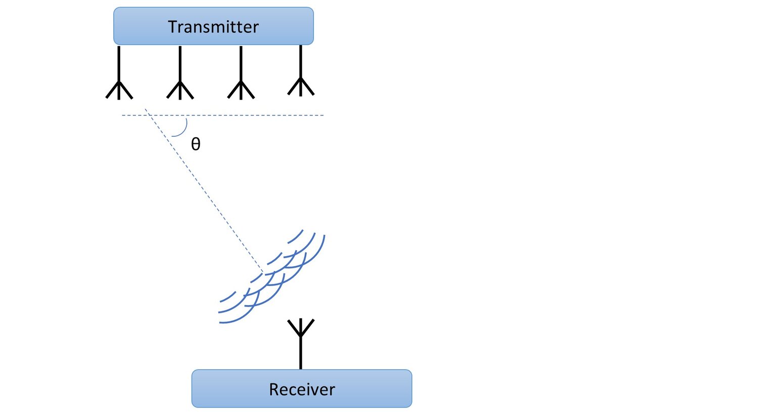
The transmitter broadcasts at the same time messages from multiple antennas that contain the CTE. Each signal message from the antennas in the array arrives at the receiver’s single antenna with a different phase shift. The phase difference is due to the distance travelled from the transmitter antennas as illustrated below:
Based on the above picture, the angle of departure θ can be calculated using the measured phase difference ψ, the signal wavelength λ and the known distance between the antennas d as:
θ=arccos(ψλ/2πd)
Multiangulation
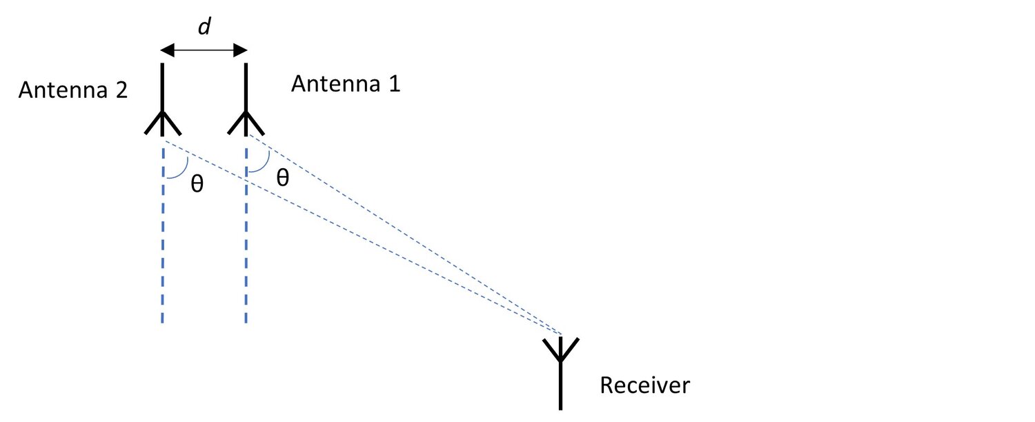
A system that can measure angles from multiple fixed points either using AoA or AoD methods can estimate device position using multiangulation (a.k.a. triangulation). Consider for example a setup where there are two fixed beacons with known positions and a smartphone that can measure angle of departure (AoD) from each beacon’s signal as illustrated below:
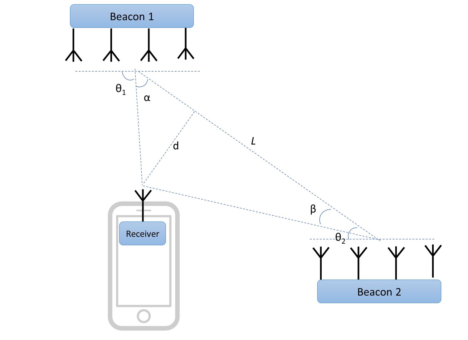
The receiver measures the angles of departure θ1 and θ2 from each of the reference beacons. Since the positions of the beacons are known, the two angles α and β can be calculated from θ1 and θ2 as well as the distance between the two beacons can be calculated as L. As a result, it is possible to construct a triangle where one of the sides and two of the angles are known, with the smartphone device at the third point. From such triangle using the Pythagorean theorem the position of the smartphone can be estimated.
Using angle of departure or angle of arrival methods for micro-location requires slightly more complicated circuitry and hardware setup, especially related to the antenna arrays. There are also additional phase difference measurements that need to be performed by the Bluetooth SoC. However, angle measurements based on the radio signal in general are less affected by the environment. As a result, using the direction-finding feature centimeter positioning accuracy can be achieved.
Smartphone Micro-Location using BT 5.1
BT 5.1 is relatively new standard. At the time of writing of this blog, there is no official support announced for the direction-finding features in iOS or Android. Many of the 2020 Android smartphones come with BT 5.1 enabled chips. However, the direction-finding functionality is not yet supported by the Android operating system.
Once implemented, the smartphones will most likely use the Angle of Departure (AoD) method to estimate direction of signals from BT 5.1 enabled beacons. This will keep a single antenna in the smartphone. The smartphone would be able to work with special BT 5.1-enabled beacons that have antenna arrays.
In addition to BT 5.1 enabled SoC, the smartphones require the corresponding drivers and firmware to do angle calculations and pass them to the applications. For AoD method to work the receiver needs to know the configuration of the transmitter antennas. It is likely that Google will add support for this feature as part of the Android OS. Apple is likely to follow suit once there is enough adoption of BT 5.1 and availability of beacons. Initially, they will likely promote the Ultra Wide Band (UWB) technology as an alternative to BT 5.1 direction-finding. Eventually, once BT 5.1 becomes widely adopted, it is likely that Apple will include BT 5.1 direction-finding support as part of the iPhones and iOS as well.
Currently there are no beacons available on the market that support BT 5.1 direction-finding feature. The beacon makers are working on adding such support. They are already integrating the Bluetooth SoCs that support BT 5.1, so it is likely that in 2021 we will see beacons that support AoD or AoA modes available on the market.
Conclusion
In order to create practical and low-cost solution for smartphone based micro-location using the new BT 5.1 directing finding feature, beacons need to be available as well as software support on the smartphone side. We expect to see beacons with the needed BT 5.1 direction support in 2021 and announcements for such support on the Android side with some beta programs demonstrating its availability.
With Apple pushing the UWB technology, BT 5.1 and UWB will compete in the next few years to become the prevailing micro-location enabling technology. BT 5.1 is likely to stay around as BLE is currently widely supported and is an accepted standard.
Let Abalta Help with Your Micro-Location Needs
To learn more about how Abalta can help solve your micro-location needs, please contact us at info@abaltatech.com.